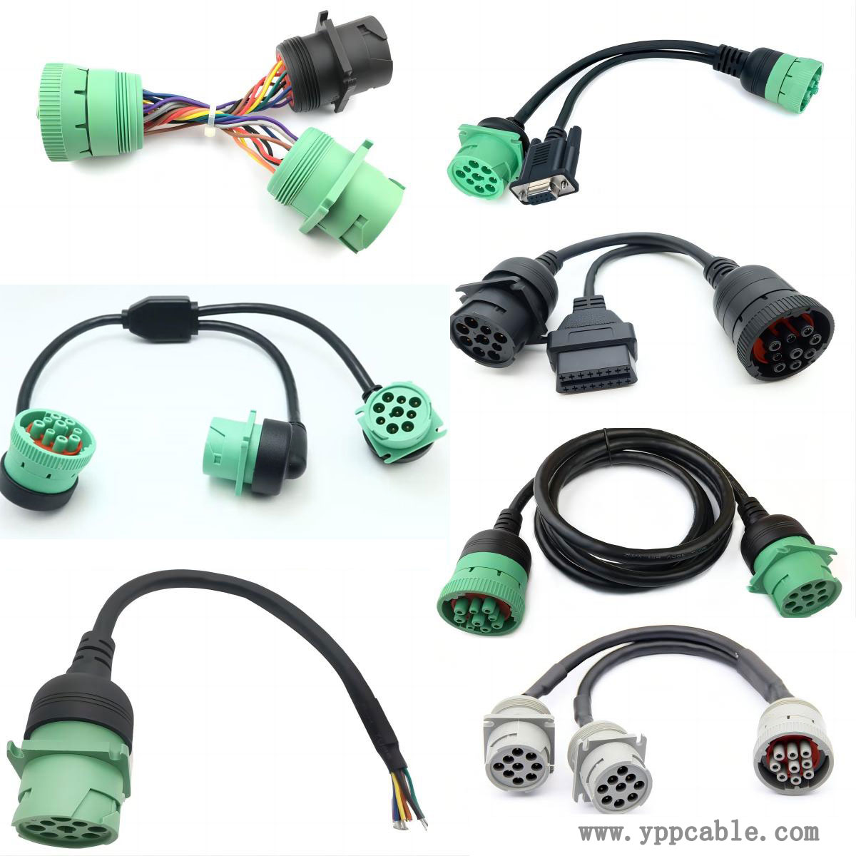
Testing method for J1939 splitter Y cable
The following is the general testing method for J1939 splitter Y cable:
Appearance inspection
Carefully inspect the outer sheath of the cable for any damage, cracks, aging, wear, etc., especially at the bent and joint areas of the cable. If the outer skin is found to be damaged, it may expose the internal wires, causing problems such as short circuits or open circuits.
Check if the cable connectors are loose, deformed, oxidized, corroded, etc. Loose connectors can lead to poor contact and affect signal transmission; Oxidation or corrosion may increase contact resistance and reduce signal quality.
Conductivity test
Using the resistance range of a multimeter, connect the red and black probes to different pins or ends of the Y cable, and measure their resistance values. If the resistance value is infinite, it indicates that there is an open circuit fault in the circuit; If the resistance value is significantly lower than the normal value or zero (except for special short-circuit design situations), there may be a short-circuit fault.
For each branch line of the Y cable, a continuity test must be conducted to ensure that each line can conduct normally.

Insulation resistance test
Using an insulation resistance tester, connect one end of the tester to the conductor of the Y cable and the other end to the outer sheath or grounding terminal of the cable, and measure the insulation resistance value. Generally, it is required that the insulation resistance value should be greater than a certain standard value. If the insulation resistance value is too low, it indicates that the insulation performance of the cable has decreased, and problems such as leakage or signal interference may occur.
Signal transmission testing
Professional J1939 protocol analyzers or oscilloscopes can be used to input standard J1939 signals at one end of the cable, and then detect the transmission of the signals at the other end. Observe whether the amplitude, frequency, phase and other parameters of the signal comply with the J1939 protocol, and whether there are any phenomena such as signal distortion, attenuation, interference, etc.
By sending signals of different types and intensities, simulate various situations in actual work, and comprehensively detect the transmission capability of cables for signals. If there is a problem with signal transmission, it may be due to the quality of the cable itself, poor connection, or external interference.
Grounding
Check if the grounding of the Y cable is good. Use a grounding resistance tester to measure the grounding resistance between the cable grounding terminal and the ground. The grounding resistance should meet the requirements of relevant standards. If the grounding resistance is too large, it will affect the safe operation of the equipment and the stability of the signal.
When conducting testing, it is necessary to strictly follow the relevant safety operating procedures and testing standards to ensure the accuracy and safety of the testing results. If there are any doubts about the test results or if problems are found with the cables, further analysis and handling should be carried out in a timely manner. If necessary, the cables should be replaced or professional technical personnel should be sought for assistance.
Contact: Kevin Yu
Phone:
E-mail: yppcable@126.com
Whatsapp:
Add: FL2,Bld 6, Hongte Industrial Park, Yongtou , Changan, Dongguan, Guangdong